
Hardware Specifications
| Vendor/Brand | Adtran |
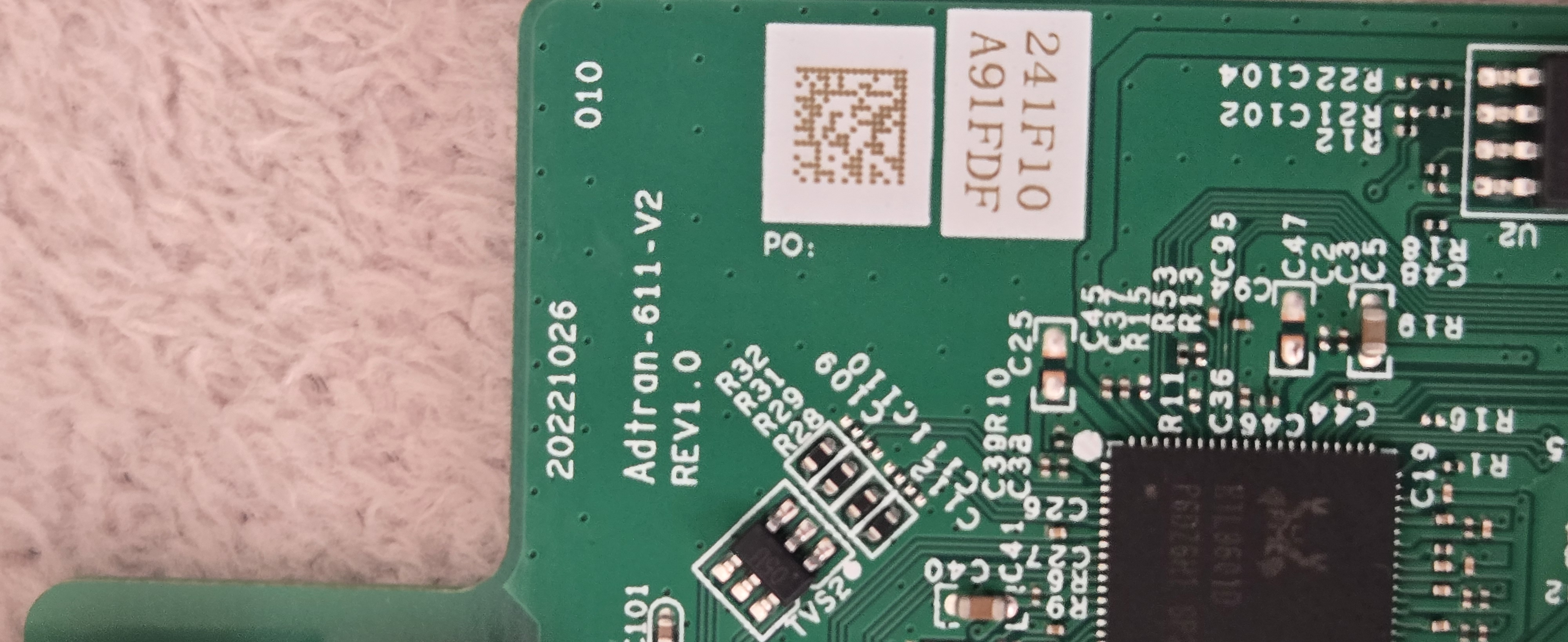
| Model | SDX 611 (Adtran-611-V2 REV1.0) |
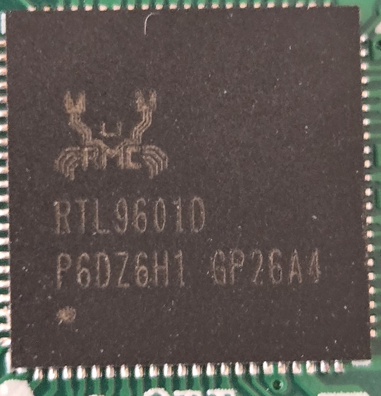
| Chipset | Realtek RTL9601D (Realtek "Luna" SDK) |
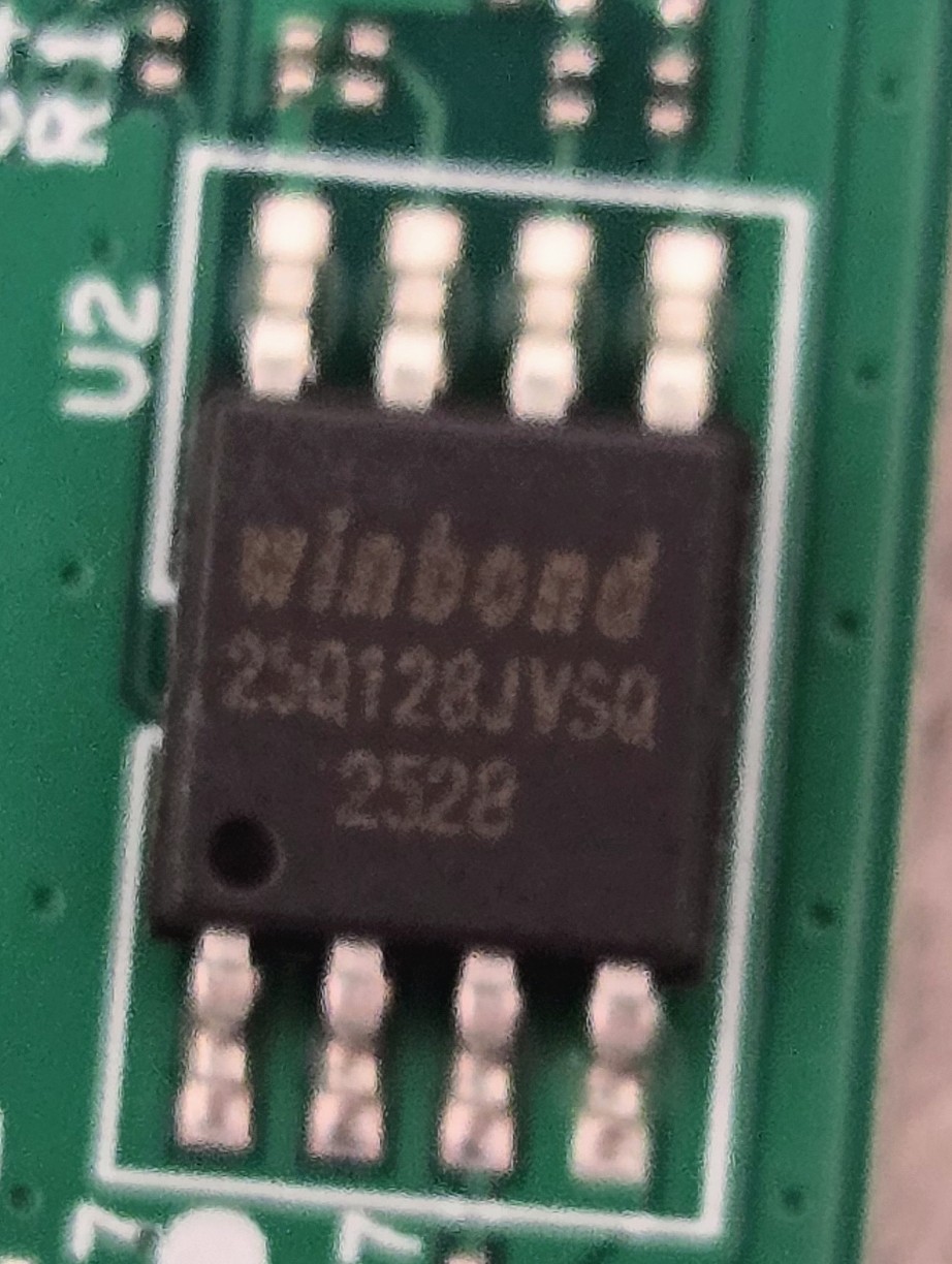
| Flash | 16 MB (Winbond W25Q128JVSQ) |
| RAM | |
| System | |
| Firmware | GRO100_ADTRAN611V2 V2.2.9.11 (built 2022-11-12) |
| Bootloader | U-Boot 2011.12.NA-g61AC973 |
| Kernel | 3.18.24 (uImage, LZMA, load address 0x80000000) |
| Root filesystem | squashfs 4.0, XZ compressed, 128 KiB blocks |
| Userland | uClibc 0.9.33.2 + BusyBox |
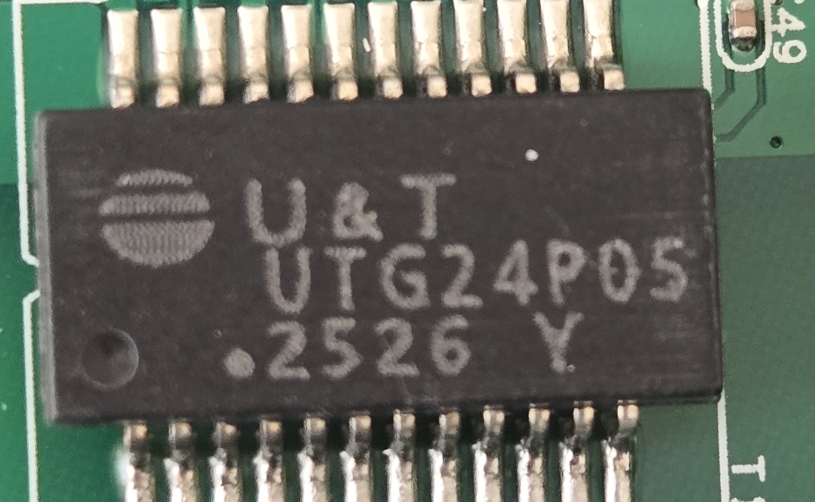
| Optics | SC/APC (U&T UTG24P05) |
| 2.5GbaseT | No |
| IP address | 192.168.1.1 (U-Boot serverip 192.168.1.54) |
| Web Gui | |
| SSH | |
| Telnet | ❌ (path present, service stubbed out) |
| Serial | ✅, no credentials needed |
| Serial baud | 115200 |
| Serial encoding | 8-N-1 |
| Form Factor | ONT |
Disassembly
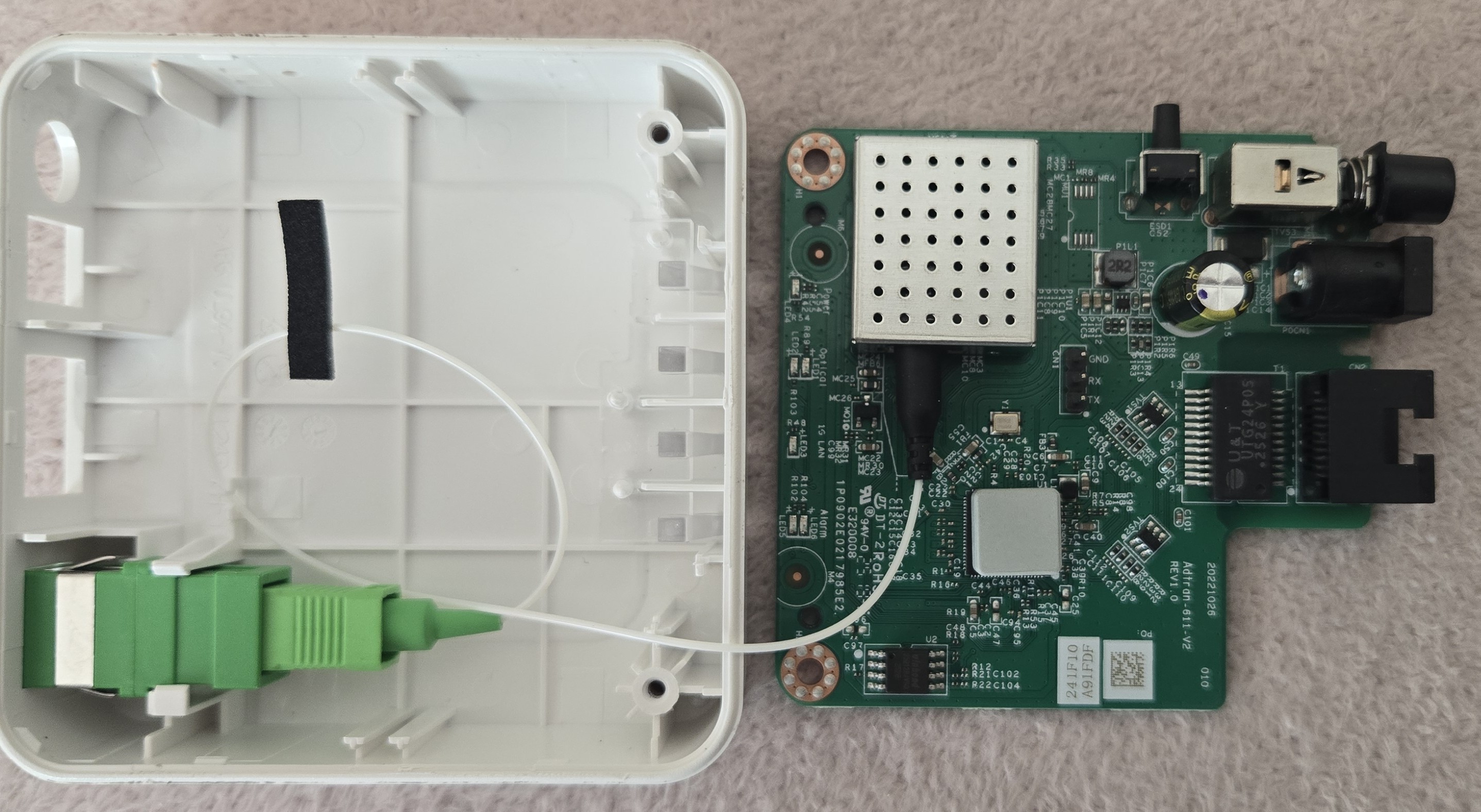
- Remove the two screws hidden under the rubber feet on the back of the unit
- Use a plastic pry tool to separate the rear cover, as it is held in place by a snap fit
Note
Be careful when prying the rear cover off, the snap fit clips can break easily.
Serial
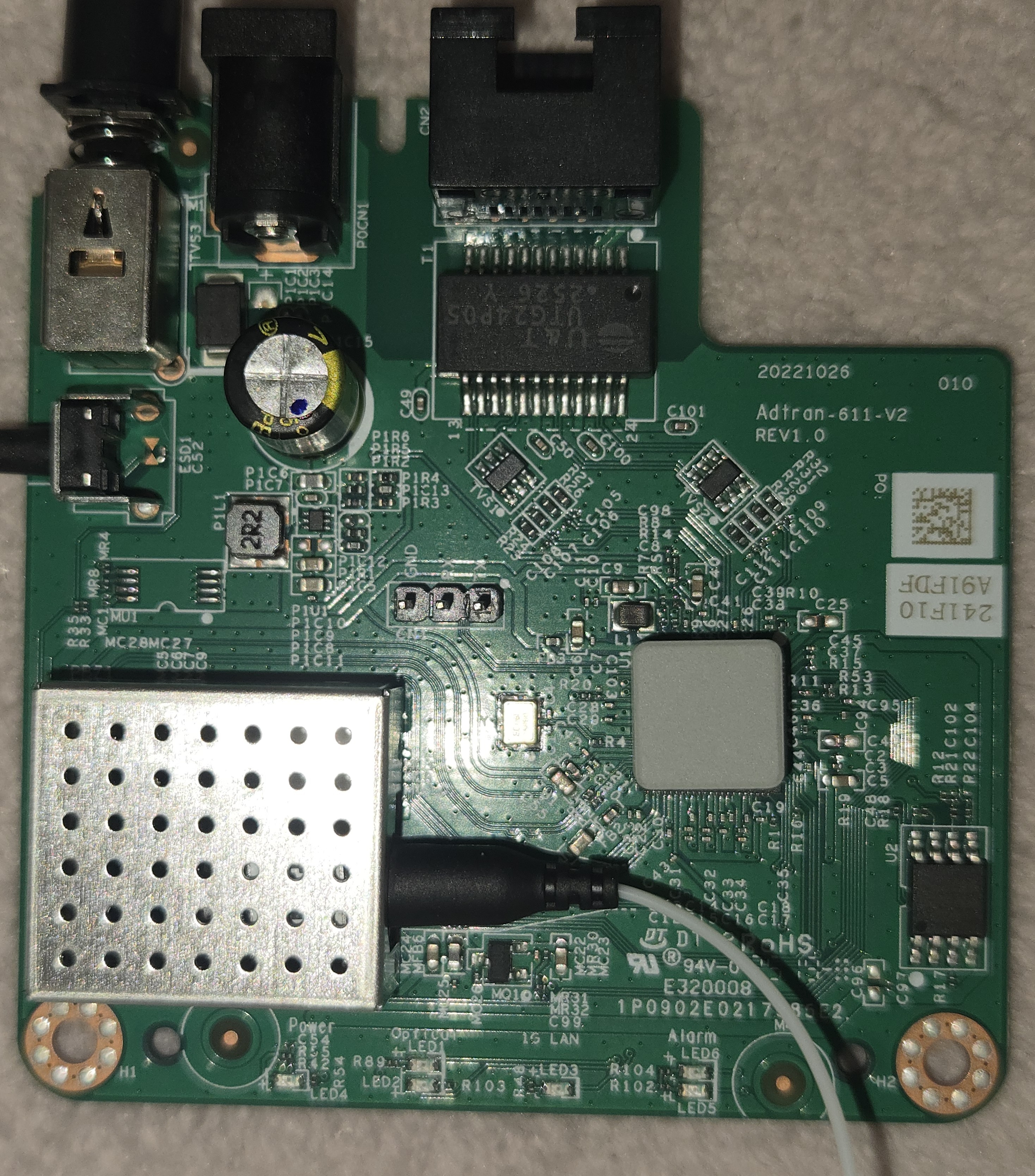
The board has GND, TX and RX headers already soldered. A USB UART adapter such as a CH340G can be used to access the serial console.
| USB TTL(UART) Adapter | Board header |
|---|---|
| GND | GND |
| TX | RX |
| RX | TX |
Note
Some USB TTL adapters label TX and RX pins the other way around: try to swap them if the connection doesn't work.
Chip identification
| Chip | Function |
|---|---|
| Realtek RTL9601D | GPON SoC |
| U&T UTG24P05 | Optical transceiver (BOSA) |
| Winbond W25Q128JVSQ | 128Mbit (16MB) SPI NOR Flash |
Firmware
Analysed from a verified full-chip read of the 16 MB SPI NOR.
Reading the flash
One 16 MB SPI NOR on the board, so a CH341A with a SOIC-8 clip is enough. Read it with the ONT unpowered and let the programmer verify: a clip read taken while the SoC is powered can be corrupt uniformly, and the verify still passes because both reads are equally wrong. A verified read of a powered-off board is authoritative over the whole address range.
Partition table
The mtd layout is not in the environment: it is compiled into the compressed U-Boot stage (an LZMA uImage at 0x15F40 that the preloader decompresses to 0x81C00000). Recovered verbatim from the image:
mtdparts=rtk_spi_nor_mtd:%dk(Boot),%dk(Env),%dk(ImageA),%dk(ImageB),%dk(Config),%dk(SECTION_EGIS),%dk@%dk(rootfs)
rootfstype=squashfs console=ttyS0,115200 softMode=%s ACTIVE=%c chiptype=RTL9601D
rootfs is given as size@offset, i.e. an alias to the root filesystem of whichever image bank is active (the same U-Boot carries fl_rootfs1 / fl_rootfs2), so it does not tile the chip on its own.
| Offset | Size | mtd | Content |
|---|---|---|---|
0x000000 | 384 KiB | Boot | SPI preloader; U-Boot 2011.12.NA-g61AC973 as LZMA uImage at 0x15F40, 71476 B, load 0x81C00000 |
0x060000 | 128 KiB | Env | U-Boot environment at 0x60000 (valid); the redundant copy is zero-filled in this image |
0x080000 | 7296 KiB | ImageA | Vendor header, kernel uImage at 0x80200, rootfs squashfs at 0x1C0000 (bytes_used 0x3E038A) |
0x7A0000 | 7296 KiB | ImageB | Identical copy of ImageA (same kernel SHA-256); rootfs squashfs at 0x8E0000 |
0xEC0000 | 512 KiB | Config | JFFS2, 4 KiB erase blocks, mounted on /var/config |
0xF40000 | 768 KiB | SECTION_EGIS | Protected parameters (product code, ADTN serial, MAC), accessed through egistool / the egis kernel module |
| alias | 0x3E038A | rootfs | 0x1C0000 while ACTIVE=A, 0x8E0000 while ACTIVE=B |
The 384 + 128 + 7296 + 7296 + 512 KiB above tile exactly to 0xF40000 of the 16 MiB, which is what makes the boundaries trustworthy rather than guessed.
Note
ImageA and ImageB hold the same firmware in this build (identical kernel and rootfs), so the second bank is a plain copy for recovery, not an A/B firmware pair.
Bootloader environment
Recovered from the Env partition (0x60000):
active_image=A          product_revision=E      bootcmd=tw_boot        bootdelay=3
baudrate=115200         softMode=NORMAL         ethaddr=00:11:22:33:44:66
ipaddr=192.168.1.1      serverip=192.168.1.54   netmask=255.255.255.0
boot_upf=tw-rtl9601d-u-boot-g1481E470F.upf
image_upf=PON699EE.2U2AD-4-TW-R01B010D29390-CN.squashfs.upf
stdin=serial stdout=serial stderr=serial link_status=DOWN
ethaddr is the Realtek reference placeholder (00:11:22:33:44:66), so the unit MAC is not stored in the environment: provisioning lives in SECTION_EGIS. active_image selects which bank the rootfs mtd alias resolves to, and bootdelay=3 is the window to interrupt U-Boot on the serial console.
Boot chain
- Preloader in the Boot partition initialises SPI and DRAM.
- It decompresses the LZMA uImage U-Boot to
0x81C00000and jumps to it. - U-Boot reads the environment (
bootcmd=tw_boot) and picks the bank named byactive_image. - It loads the kernel uImage (
0x80200/0x7A0200, LZMA, entry0x80000000) and boots withrootfstype=squashfs console=ttyS0,115200 ... chiptype=RTL9601D.
U-Boot also offers a console prompt (* Ctrl+C -- Enter console terminal *) with commands that rewrite the flash: mp/xmodem for the SPI NOR preloader and update kernel and rootfs by tar|vmimg format, which writes to the partitions above.
Root filesystem notes
/etc/inittabruns/etc/init.d/rcSand then-/bin/shas a respawned root shell on the serial port, with no login prompt./etc/init.d/S50telnetdis an empty stub:telnetdships inside BusyBox but nothing starts it in this firmware, which is why telnet is listed as unavailable above. Any writable-partition hook can start it./etc/init.d/S02mountconfigmounts the Config mtd as JFFS2 on/var/config; if the mount fails it runsmtd eraseon that partition and mounts again, so a corrupt config falls back to defaults on the next boot./etc/init.d/S95startsspcopies/etc/default/passwdto/var/passwdand installs the SSH host keys from/var/config. The password used by the box therefore comes from the config partition, not the squashfs./etc/init.d/S05kernel_debugwrites kernel core dumps into/var/config/kernel/, i.e. into the writable config partition./etc/init.d/S04boardinfoinitandS40networkread the product code throughegistool -pand branch oncodeExtend:0x2is the 2.5G port map, everything else the 1G one. Board identity (product code, serial, MAC) comes fromSECTION_EGIS, not from U-Boot.- The dropbear RSA/DSS host keys are baked into the read-only squashfs (
/etc/dropbear_rsa_host_key,/etc/dropbear_dss_host_key), so every unit running this firmware build shares the same SSH host keys. - The GPON/OMCI stack is present as
libgpon_client.so,libonumgr_client.so,libonumib.so,libhal_gro100_adtran611v2.so,libhal_r29601d.soplus thebosa/bosalBroadcom optical libraries, with a CTC-style web UI (acl_setup.html,ctc_config.js,hide_loid_mac.js, …) shipped in the rootfs.
Config partition
0xEC0000, JFFS2 with 4 KiB erase blocks (a cleanmarker at the head of every block marks the extent). It is mounted on /var/config and contains among others omcimib.conf, run-syslog.sh, resetcfg, g.bobparams.bin, the kernel core dump directory and the persistent .dropbear_*_host_key copies.
omcimib.conf is an OMCI MIB store: a container of MIBT records, each with a template name (adtran_6010), a timestamp and the ONT identity — the 4 ASCII bytes ADTN followed by the binary GPON serial and the unit MAC. Recording the GPON serial / MAC of a specific unit in a public page is not useful to anyone else, so the field layout is documented and the values are left out.
Notes and anomalies
0x061000-0x07FFFF(the redundant U-Boot environment sector) reads back as0x00, not the0xFFof erased NOR. It does not affect booting — the primary environment at0x60000is valid — but "erased flash is all0xFF" does not hold in this image.- The tail of the flash (
0xF41000onwards) is a mix of erased and zeroed sectors with only a few KB of non-blank data, so theSECTION_EGISextent above is derived from the cleanmarker boundary at0xF40000rather than read from themtdpartssizes, which are substituted at runtime (%dk).
Miscellaneous Links
- ispreview.co.uk
Adtran SDX 611- Adtran SDX 610 family datasheet
- sdx611-firmware — recovered mtdparts, flash map and boot chain